
Deburring bores that intersect and cross inside workpieces is difficult. In a study, workpieces made of free-cutting or heat-treated steel and a high-strength aluminum alloy, all of which had extremely complicated deburring situations, were deburred and compared using different methods. Second and last part of the series.
High-pressure water jet deburring
Deburring with or by high-pressure water jets was scientifically investigated decades ago [14] and has become widespread in some commercially available systems and applications [15-19]. This process is less about targeted edge rounding and more about removing and flushing away burrs using the high kinetic energy of a water jet at a high flow rate and therefore high speed. Although it is technically possible to remove burrs right into the theoretical edge, resulting in a rough, eroded edge rounding (Fig. 21), this process is generally used to remove burrs to such an extent that no more material particles can become detached (Fig. 22). In general, high-pressure water can be used for cleaning, deburring or cutting, although the required pressure and flow rates and therefore also the pressure generators differ. Deburring is carried out at pressures below 1,000 bar and flow rates of up to 100 l/min (for cleaning, the values are significantly lower). Pressure intensifiers are usually used for cutting (soft materials with pure water, hard metals, ceramics, glass or stone with abrasive admixtures), which generally generate pressures of up to 4,000 bar at flow rates of up to 5 l/min. The particular advantages of this process are the fast processing without thermal impact, the reliable removal of certain types of burrs and the simultaneous cleaning effect. Disadvantages are the targeted approach of each burr with a lance when the burrs are inside the workpiece, the necessary clamping of the parts and the relatively high price of the systems.
 Fig. 21: Workpiece made of 20MnCr5, deburred by high-pressure water at a pressure of 700 bar, a special cleaning nozzle in about 10 s
 Fig. 22: Workpiece made of 20MnCr5, deburred by high-pressure water with a pressure of 700 bar, a special cleaning nozzle in about 10 s
Final preliminary considerations for the tests
To summarize the deburring processes discussed in the last sections, it can be stated that all of them are suitable for processing the burrs shown earlier, but not every process is suitable for every burr and not for every desired deburring quality.
 Fig. 23: Bore exit deburred with the Burr-Off tool in the machining center
From today's perspective, deburring in the machining center appears to be the most suitable. For the robot, the investment and the additional work step are less suitable, for the ECM, TEM and high-pressure water jet deburring processes, the system costs and also the additional work step. The only positive aspect of the TEM process is that all burrs are deburred simultaneously in a single operation (consisting of two "shots") and without any further measures apart from cleaning, with a dimensionally adjustable edge rounding, and no further reworking is required apart from subsequent passivation.
 Fig. 24: Bore exits deburred with the Burr-Off tool in a hand-guided machine
Deburring tests with special tools
In a first step, tests are carried out with the Burr-Off tool using the processes that are to be regarded as preferred according to the last section(Fig. 17, bottom row, Galvanotechnik 9/2022, p. 1183) [6]. The burrs selected were of the type shown in Fig. 4 or 6 (Galvanotechnik 9/2022, p. 1180), but with diameters of 4 and 8 mm (tools CP10 and CP20). The tests were carried out on the machining center with a speed of 1,590 min-1 and a feed rate of 115 mm/min as well as with a hand tool with similar settings. The deburring result was good in the machining center (Fig. 23), both on steel and on an aluminum alloy. The machining time in the tests was around 50 s for two holes. How many holes can be deburred before wear occurs could not be determined due to the small number of tests. As only just under 5 minutes are required for the entire production of the tested part, the increase in machining time should not be neglected and could possibly be shortened by using a higher feed rate. In this case, this tool was not so suitable for deburring with a hand-held machine because the edges are very quickly gripped too tightly (Fig. 24) and the employees would possibly require extensive training.
Similarly positioned burrs were also deburred in the machining center using the HSD tool(Fig. 17, top row, right) [6]. With this tool, deburring is carried out with several cutting edges, which are retracted to the burr location when inserted into the workpiece and are extended for rotary deburring (black arrows in Fig. 25) by a medium under pressure, e.g. cooling lubricant (green arrows in Fig. 25). The examined burr was located at an intersection of a bore with a recess. Two tests were carried out at a speed of 1,000 rpm and feed rates of 160 and 60 mm/min. No satisfactory results were achieved with the higher feed rate, but satisfactory results were achieved with the lower feed rate (Fig. 26).
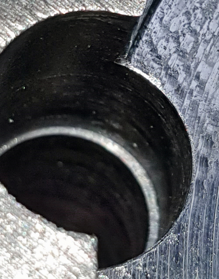
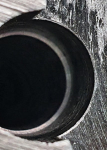
Fig. 26: Deburring result with the HSD tool
As with the last tool examined, it can be summarized that the tool is well suited for certain burrs, but the tool is more expensive than the last tool examined. Deburring takes about 20 seconds and the suitability of the tool also depends on the number of workpieces to be processed.
Finally, tests were carried out with ceramic mounted points with a flexible shaft(Fig. 17, bottom row, with orange ball or blue cylinder). The workpiece was made of mild steel and the burrs corresponded approximately to those in Figures 3 and 5 or 8 or 12, Galvanotechnik 9/2022, p. 1180, p.1181). Spheres with diameters of 6 and 10 mm were used in the machining center as well as with hand-guided machines, and a cylinder with a diameter of 4 mm (only with hand-guided machines). A grit size of 220 was used for all tools. Speeds between 5,000 and 8,000 rpm were used in the machining center; when pressing on the abrasive balls, 5 N should not be exceeded and the burrs should not be significantly larger than 0.2 mm. It turned out that it was difficult to approach the burrs with the machine's program alone in order to achieve a good result and visual improvements had to be made.
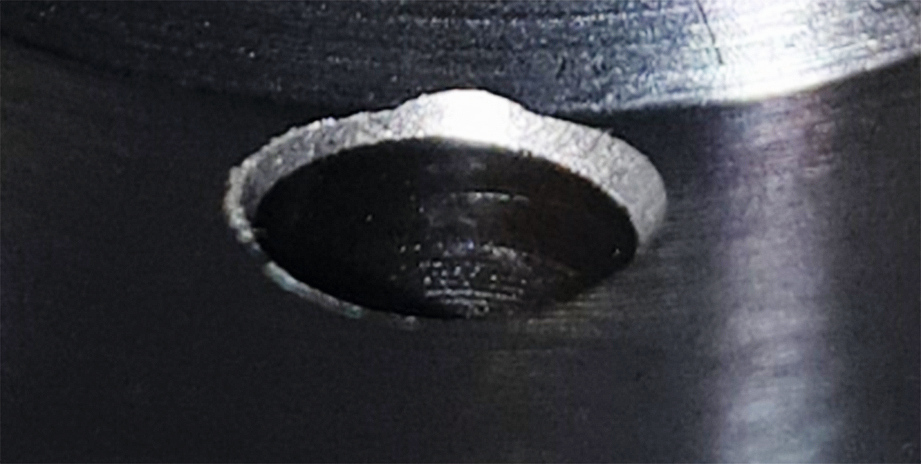
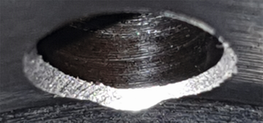
Fig. 27: Bore exits deburred with ceramic grinding pins; above with the 6 mm diameter ball, below with 10 mm
In both cases, the chamfer applied was somewhat too large for the application (Fig. 27) and although the tool with the relatively thin shank enabled good accessibility both in the machining center and with the hand-guided machine, it generated vibrations during machining. Based on the handling observed, use in the machining center does not appear to be optimal, with the hand-held machine only if the burrs are not too large. This would then require a coarser grit, which was not investigated.
Deburring tests with the thermal-chemical deburring method (TEM)
As this deburring method is very promising based on the considerations regarding the suitability of the individual processes, it was selected for further tests. Six parts were selected for these tests, which were taken from the same series as the ceramic mounted points. Therefore, the burrs were also produced by the same processing. The workpieces were deburred or machined twice in succession, with a rusty coating forming after the first shot, which was transformed into a black oxide coating after the second shot to allow easier cleaning. The deburring effect was very good on all burrs on the workpiece (Fig. 28).
 Fig. 28: Deburring result from thermal-chemical deburring
 Fig. 29: Smooth-rolled bore for investigating the effects of deburring with the thermal-chemical deburring method; part cut open for investigation As the entire workpiece is machined in this process, some other features of the workpiece had to be examined more closely. There were surfaces that were tolerated with a valueRa < 1.2 µm and those that were tolerated withRa < 0.8 µm, as well as smooth-rolled surfaces whoseRa value must be between 0.1 and 0.2 µm. All values were still within tolerance after deburring, although the surfaces became slightly smoother in two cases and slightly rougher in one case. On one surface, the material contact ratio Rmr should be between 50 and 70 %. After deburring, however, all values were higher, although in one of the parts this was already the case before deburring. These roughness measurements were carried out with the MahrSurf PS10.
Finally, there were further concerns: it would theoretically be possible for the smooth-rolled surface to change due to the effect of the combustion. In the same way, any existing formed internal threads could be damaged because the thread tips on the core diameter have a gap due to the thread forming. These tips could be damaged by deburring because their mass is smaller, they cannot dissipate the heat into the material and would therefore burn like a burr.
Special attention was paid to the examination of a smooth rolled surface. This inner surface of a 16 mm diameter bore was examined in detail both before and after deburring. Figure 29 shows a section of the steel workpiece, which was cut open so that it could also be visually inspected with microscopes. In Figure 30, the inner surface was photographed at 20x magnification with the Keyence VHX-7000 digital microscope and it can be seen that it is very regular and in accordance with the specifications.
 Fig. 30: Inner bore surface from Figure 29 at 20x magnification
A classic roughness measurement with the Jenoptik T8000CR stylus instrument also shows that the surface has been optimally machined (Fig. 31). Both the roughness profile and the material contact ratio curve or the amplitude density distribution show that there are predominantly a few depressions and hardly any or only low elevations - a typical plateau profile that can easily be produced by smooth rolling. This is also confirmed by the valueRSk = -2.28. Further roughness values are Rz = 1.77 andRa = 0.15 µm, the profile contact ratio at a depth of 0.5 µm was Rmr = 37 % and at a depth of 0.528 µmMr1 = 43.77 % (Fig. 31).
 Fig. 31: Roughness measurement longitudinally in the bore of Figure 29 or 30
 Fig. 32: Workpiece from Figure 29 at 100x magnification after deburring by TEM The parts deburred by TEM show no changes in the surface that would rule out the use of the process (Fig. 32). This was confirmed by examining a section of the inner surface of the bore using the Phenom ProX scanning electron microscope from ThermoFischer (Fig. 33 and 34). These images show that although there are clear remnants of the deformation from burnishing (especially in Fig. 34; rolling direction is from bottom right to top left in all images), these were not affected by the burning of the burrs. Provided there are no formed threads in the parts, it can therefore be concluded from this investigation that smooth-rolled surfaces do not prevent the use of TEM deburring.
Summary
The investigation of some selected deburring processes for a given range of workpieces has shown that there is no preference for one process and that some of the processes are possible in any case. For the range of workpieces in question, processes were selected in advance that were likely to be suitable based on the expertise of the planning engineers and others were excluded that were highly unlikely or objectively unsuitable for the workpieces.
The predominant process up to the time of the new considerations was manual deburring, which almost always works in cases of doubt, but is expensive and does not always lead to good results. Incentives to use a new process include the capacity of both the production facilities as a whole and the manual deburring department in particular, as well as the costs of the previous procedure, which are to be reduced. All these aspects must also be taken into account when selecting possible new processes, with the added factor that a new process usually requires investment, whereas maintaining the current processes does not.
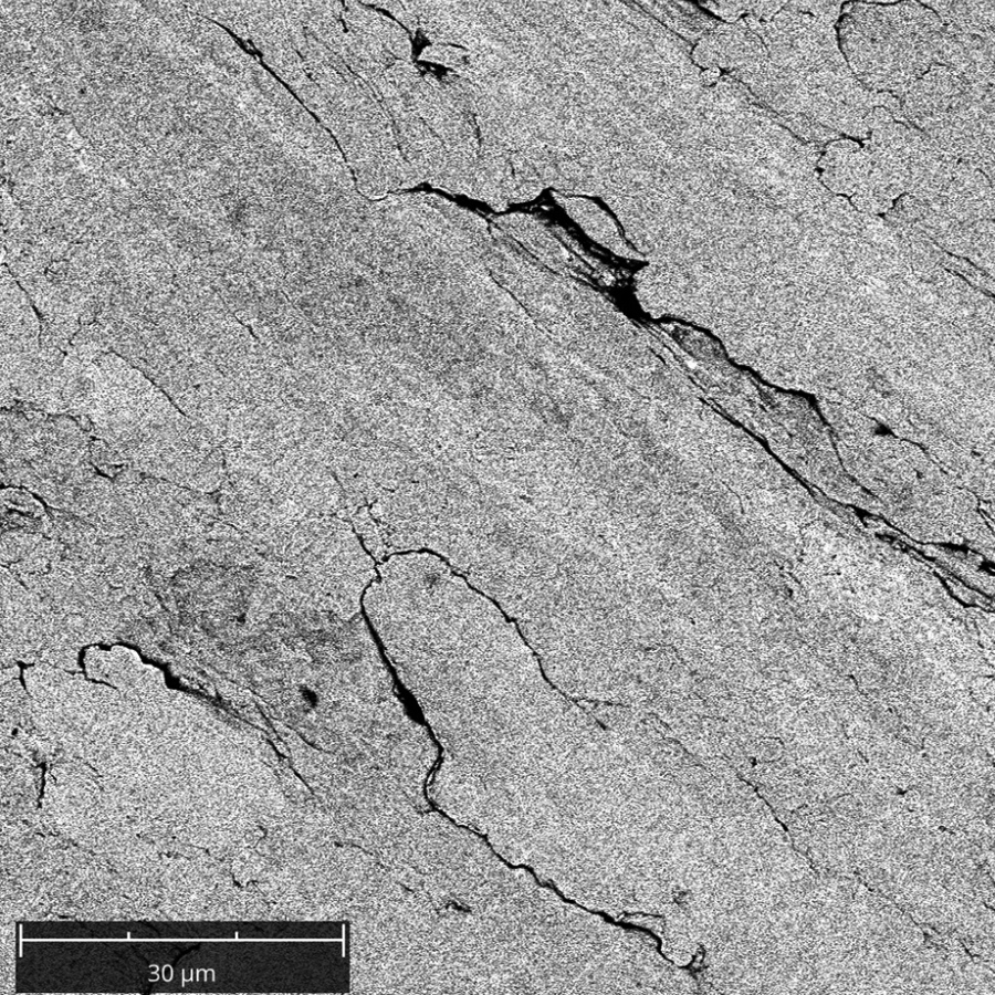
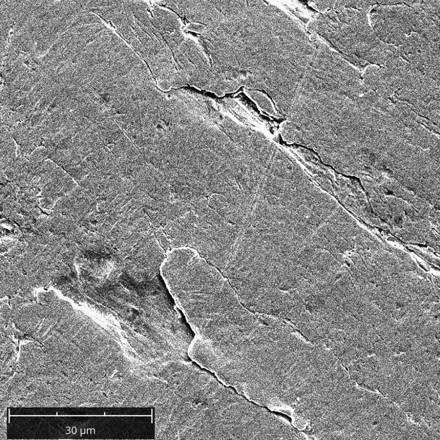
Fig. 33a and b: Inner surface of the bore from Fig. 29 after deburring by TEM at 2,900x magnification with secondary electrons (left) and with the topography method (right; similar to illumination from the top right)
In order to be able to make a selection as objectively as possible, a systematic approach is suitable. Criteria that should be weighted include, for example
- deburring quality including process reliability
- Integration into the existing production process
- the space required for any new systems
- the flexibility for a range of workpieces
- the personnel requirements
- the cycle time and
- the required investment.
 Fig. 34: Inner surface of the bore from Figure 29 after deburring using TEM at 6,900x magnification with secondary electrons Different people in the company who are responsible for different areas weigh these or additional aspects differently. For example, those responsible for costs will give more weight to the criteria at the bottom of the list and people from quality assurance will give more weight to the criterion at the top. In this example, the weighting was carried out by three different people from the areas of milling production, design and sales. Process reliability was rated highest by one person and deburring quality was rated highest by the other two. The space requirement for a possible new system was ranked last by two people and also on average.
The evaluation of the processes described in more detail above also differed among the evaluators: One employee rated robot-assisted deburring first and the other two rated manual deburring last, not least because of its great flexibility and the avoidance of investment. However, this consideration also led to the possible use of new tools, such as those from the range shown in Figures 16 and 17 (Galvanotechnik 9/2022, p. 1182/1183), together with hand-guided machines. In addition, the extent to which deburring can be integrated into the machining centers without irresponsible additional work should be examined for each workpiece in order to reduce the effort required for manual deburring. It was previously stated that purely mechanical processes require a larger investment, but are not necessarily suitable for all burrs. With ECM, there is also the occurrence of larger burrs, as shown in Figures 7-9 and 13 (Galvanotechnik 9/2022, p. 1181/1182), which can lead to short circuits when approaching with the cathode (see Fig. 20, Galvanotechnik 9/2022, p. 1184). It would still be possible to outsource deburring and use the facilities of service providers. In the present case, however, this is prevented by the excessively narrow time window between the order being placed by the customer and the parts being delivered to the customer.
Literature
[1] Schäfer, F.: Untersuchungen zur Gratbildung und zum Entgraten insbesondere beim Umfangsstirnfräsen, University of Stuttgart, Dissertation, 1976
[2] Fertigungstechnik und Betrieb 28 (1987), No. 1, 7
[3] Hauke, T.: SWMS Systemtechnik Ingenieurgesellschaft mbH, https://www.swms.de/blog/autonomes-entgraten-von-strukturbauteilen/, 4.1.2021, viewed on 30.10.2021
[4] Itasse, S.: Produktion & Fertigung, Maschinenmarkt, Report on Deburring EXPO 2015, https://www.maschinenmarkt.vogel.de/viele-verfahren-ermoeglichen-erfolgreichesentgraten-a-505956/, 28.9.2015, (viewed on 17.9.2021)
[5] N. N.: One Operation, The tools for machining bores forwards and backwards in one operation, Company brochure of Heule Werkzeug AG, Balgach, Switzerland, V3.0, 05.2019
[6] N. N.: Back-Burr Cutter & Path deburring system; GMO deburring tool, HSD High Speed Deburring, deburring and chamfering tools, ceramic deburring brushes & mounted points, company publications of KEMPF GmbH, Reichenbach an der Fils, no year (viewed 11.11.2021)
[7] DIN 8590, Removal manufacturing process, Beuth Verlag, Berlin, September 2003
[8] Beier, H.-M.; Nothnagel, R.: Praxisbuch Entgrattechnik, 2nd edition, Carl Hanser Verlag, Munich, 2015
[9] Kieser, A.: TEM Basic Information, Kieser TEM Consulting, Version V2, 1.9.2009
[10] N. N.: Thermal deburring, company publication of ATL Anlagentechnik Luhden GmbH, Luhden, 08.2013
[11] N. N.: Defined deburring, ECM-Team GmbH Entgrattechnik, Buxheim, 10.2012
[12] Kör, M. (stoba Sondermaschinen GmbH): pers. Comm. 21.7.21
[13] Thilow, A.: Deburring technology, 4th edition, expert Verlag, Renningen, 2012
[14] Schlatter, M.: Deburring by high-pressure water jets. Springer-Verlag, Berlin Heidelberg New York Tokyo, 1986
[15] N. N.: Pure perfection, company publication of Piller Entgrattechnik GmbH, Ditzingen, no year
[16] N. N.: Highly efficient multifunctional cleaning system, catalog of Sugino Machine Ltd, Tokyo, June 2017
[17] mo Magazine for Surface Technology, Special, 5 (2016), 22-24
[18] mo magazine for surface technology, 72 (2018) 9, 56
[19] mo Magazine for Surface Technology, Special, 75 (2021) 10,39
