The steam generation of the surface cleaning process originates in the boiler of the dry steam cleaning system. In this section, you can read which boiler designs were considered and which was ultimately determined to be the most favorable solution.
Steam generation in the boiler and the closed water circuit
The boiler is the heart of the steam system. The modern boiler, which is insulated against heat loss to the environment, is heated by a natural gas burner. Heated flue gas flows upwards through the boiler tubes. In a commonly used model boiler (Fig. 1), the hot gases are transferred from the burner into the 1st level tube and moved in the direction of flow up to 3 times through a series of many thin tubes (2nd and 3rd level) in order to achieve maximum heat transfer through the tube surfaces to the surrounding boiler water.
At the highest point of the boiler, the steam outlet from the boiler is mounted through a valve in the boiler ceiling. The control of the entire generator system is explained elsewhere.
The feed water contains mineral particles, salts. These are accelerated with the steam bubbles and penetrate the water surface. The water envelope surrounding them evaporates and the steam flow takes the now free salt particles with it. Various salt deposits become visible in practice. If these are to be reduced, the feed water must be low in salt and also filtered using reverse osmosis. As these processes are complex in practice, the sludge layers that form in the bottom of the boiler are continuously drained. This should be part of the operation; failure to do so will result in clogging of nozzles and orifices.
It is well known from practical experience that dry steam is not completely pure and is not free of mechanical particles. In flake form, the dirt particles or salts can migrate further towards the nozzle and are then present as particles on the test filter of a residual dirt analysis.
Until now, it was not possible to explain the entrainment of water droplets by the flowing steam, in fact it was impossible. Nevertheless, the measurable moisture will visibly increase from a certain load on the steam cleaning system. This is explained by the separation of steam and water on the water surface.
On the heating surface, the steam is generated in the form of bubbles and rises to the water surface due to its buoyancy. When penetrating the surface of the water, which has its own specific surface tension, the steam bubbles are burst, or they are lifted up by the surface tension of the water surface and enclosed by it.
If the vapor bubbles are destroyed, many of them, turbulence is created, water droplets are released from the water surface and propelled upwards. A layer of rising and falling water droplets forms. When the steam space is low, water droplets manage to leave the boiler through the outlet of the boiler as water droplets embedded in the flowing steam. Reflective surfaces in the direction of steam extraction from the steam generator separate the water droplets from the dry steam.
The situation is different if salt or particles have been added to the water, i.e. the normal case. In this case, the surface skin of the water is lifted without immediately tearing, and many then form a foam surface. The amount of steam and the type of salts or particles determine the foam intensity and thus the moisture in the steam. Studies on foam formation, the desired foam formation, provide detailed information on this process.
Both models allow the moisture to increase as the amount of steam extracted increases.
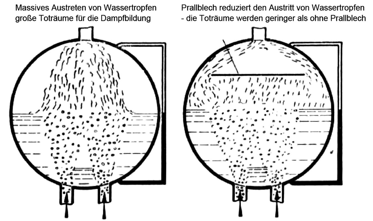 Fig. 2: Steam space with water droplets - outlet and dead spaces of steam formation
The development of a new type of steam generator structure for the tests is based on historical investigation documents and test series carried out prior to this work. The main design features are now shown.
The corresponding load limit is determined for a certain steam space height. As the height of the vapor space changes, the load-bearing capacity changes proportionally without any measurable increase in moisture. The height of the steam space determines the humidity of the escaping steam at a comparable load. For this reason, a high steam space is designed in the boiler structure.
The diameter of the steam boiler should be small due to the dead spaces created, but high above the water surface. Baffle plates or lateral discharge of the steam make better use of the steam space, increasing the load capacity of the system without increasing the humidity.
The permissible load without increasing humidity is constant at steam pressures from 4 bar upwards. For this reason, the investigations in this paper are carried out in pressure ranges between 4 and 9 bar [1].
In practice, a close-meshed metal sieve (Fig. 2) with a mesh size of 1 mm is recommended as a baffle plate. The water droplets get stuck when trying to penetrate the baffle plate and fall back. The metal screen prevents droplets from passing through by forming droplets. Wet vapors are effectively condensed through a close-meshed sieve.
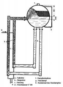
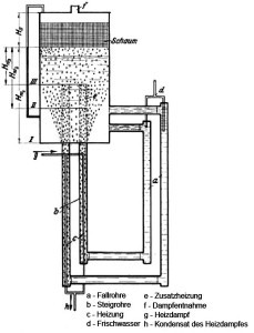
This design (Fig. 3) must be discarded as massive foaming is undesirable.
The design shown in Fig. 4 is rejected due to foaming and insufficient heat distribution, dead spaces in the downpipe area. The spherical shape is not helpful for low-droplet steam generation. The tests were carried out with a glass sphere.
For reasons of manufacturing technology, cylindrical vessels (Fig. 5) are easier to produce. Therefore, structures made of cylindrical tubes are considered in the literature and investigated in the laboratory. The solution found in the literature includes the foam formation and the lower dead spaces.
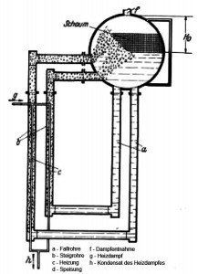
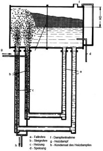 Fig. 7: Steam boiler with heated water flowing in from below, transverse cylinder shape; return inlet from belowThevariant shown in Figure 6 is a development of the solution in Figure 5. However, the formation of foam and the high production costs lead to the rejection of this solution.
The solution in Figure 7 shows the horizontal cylindrical design. The downpipes and position of the heater are unfavorable, as this results in very heavy foaming and many water droplets in the extracted steam.
The arrangements of the boiler components are chosen differently; the most energy-efficient solution and the solution with maximum steam yield and the lowest amount of water droplets in the working steam were determined in the tests. The results and our own test results from variations indicate a combination of several details as the optimum solution.
For the application from 7 kW to 30 kW heating capacity, the design in Figure 8 was determined to be a favorable solution. The arrangement of electrically staged heated tubes in the outer ring, mounted like columns around the connecting central tube, allows the water to circulate in the steam generator. Hardly any visible foam forms on the water surface. The superheated steam / working steam at 180 to 200 °C is discharged to the side (see Fig. 8).
The feed water is supplied in treated form or is treated in the separate system. The main properties of the feed water are created during treatment. The quality of the water that is fed into the boiler is important. It must be kept at the correct temperature, usually around 80 °C, in order to avoid thermal shock to the boiler when topping up during operation in the heated boiler. It must also be of the correct chemical and mechanical quality to prevent damage to the boiler. The water hardness as a measure of calcium, magnesium, potassium etc. should be less than 2 °dH. The mechanical cleanliness of the water does not include particles with a dimension of more than 100 μm. Silicates and metal shavings also do not belong in the boiler. This means that the storage tank and the boiler with the connecting piping systems have been thoroughly cleaned after production and machining. Only multiple blind tests with proof of cleanliness ensure the original condition of the "hydraulics". Steam systems should comply with the rules of hydraulic cleanliness.
A safe way of first filling the system is to filter the feed water through membranes, reverse osmosis, anion and cation exchangers with downstream membranes. The last filter element before entering the system must be a membrane, absolute filter fineness 10 μm and smaller. Glass membranes from the chemical industry have been used here.
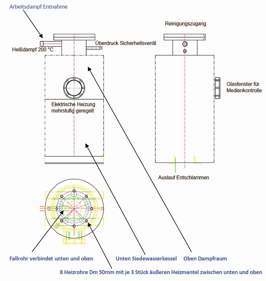 Fig. 8: Hannemann boiler design for 7 kW to 30 kW heating capacity and max. 210 °C steam at 10 bar (atü)
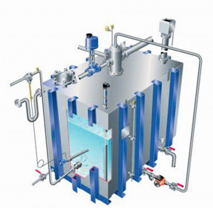 Fig. 9: An ingenious system, a storage tank Figure 9 shows a possible industrial design. The important thing here is heating with steam from your own production. The condensate water reaches the receiver tank at approx. 60 °C-70 °C, and only little additional heating is required. Heating takes place with a steam jet pump, a combination of fresh water supply and heating of the fresh water. The mixture of steam and cold fresh water degasses the fresh water. The mixture in the storage tank is a helpful side effect.
The water can be heated during operation by steam injection and kept at a temperature of 80 °C. This design is cost-intensive and was too complex for the tests carried out. However, this technical solution served as an inspiration for the design of the equipment.
Drinking water is not suitable for boilers and can quickly lead to foaming and a falsified increase in the measured values. The efficiency of the boiler would be reduced and the steam would become dirtier and wetter. In addition, the service life of the boiler would be reduced. The water must therefore be treated with chemicals to reduce the chemical impurities. The drinking water is chemically treated using upstream anion and cation exchangers. Alternatively, the condensate is regularly desludged. In the test plant, sludge was regularly removed once a day after the tests. The feed pump feeds the feed water into the boiler and the control system monitors the fill levels. Heating the feed water in the feed tank reduces the amount of dissolved oxygen. A minimum quantity of 1 to 2 mg/L oxygen should remain in the feed water so that the metal surface of the steam generator can form an oxide layer and/or magnetite - as a chemical protective layer. The steam generator is made entirely of acid-resistant 18/10 chrome-nickel steel v2A.
Made of iron and oxygen at temperatures from / higher than 200 °C:
3 Fe + 2 O2 → Fe3O4 magnetite or trie iron tetraoxide
Made from iron and water vapor at temperatures below 560 °C
3 Fe + 4 H2O→ Fe3O4 + 4 H2
From iron III oxide and reduction with hydrogen
3 Fe2O3 + H2 → 2 Fe3O4 + H2O
It is well known from practice that the boiler bottom should be conical. A dished bottom was therefore selected for the boiler. Various particles settle on the bottom due to gravity. For this reason, the bottom is designed without circulating flows. The sediment should be drained once or twice a day in batches. It is essential for the drain valve to function reliably - no jamming due to mechanical particles. The open drain creates a vortex on the dished end. The drain valve is fixed in the opening cross-section, the maximum opening is permanently installed. Sudden loss of boiler water during blowdown in a short time means more steam generation in the boiler due to pressure loss. This starts a spiral that can lead to the boiler bursting. Only small quantities of boiler water with sludge are drained per time unit!
The chemical dosing of boiler feed water softeners leads to suspended solids in the boiler. These inevitably collected at the bottom of the boiler in the form of sludge. The sludge was removed manually using a sludge removal process. The boiler attendant plays a key role in opening a blowdown valve for a set period of time, usually at least once a day. Other impurities remain in the boiler after treatment in the form of dissolved substances. Their concentration increases when the boiler generates steam. The boiler is flushed regularly to keep the concentration low.
This keeps control of the total dissolved solids (TDS control). This procedure is carried out by an automatic system realized either by a probe inside the boiler or a small sensor chamber that uses a sample of boiler water to measure the TDS in the boiler. Once the salt content reaches a set point, a controller signals that a valve is opened to remove the salt for a set period of time. As lost water is replaced by feed water with a lower TDS concentration, the total boiler TDS is therefore reduced. The automatic system was not installed. This process was carried out once a day by boiler attendants, i.e. at least 1/3 fresh water from the receiver was topped up after blowdown. The feed water was topped up with fresh water from the mixer tap as required. The boiler control system has many variants.
Part 7 presents tested and suitable versions for heating outputs of 7-30 kW.
Literature
[1] Jakob, M.; Erk, S.: Der Wärmeübergang beim Kondensieren von Heiß- und Sattdampf, Mitteilungen aus der Physikalisch-technischen Reichsanstalt, Heft 310, VDI-Verlag Berlin, 1928 H4


