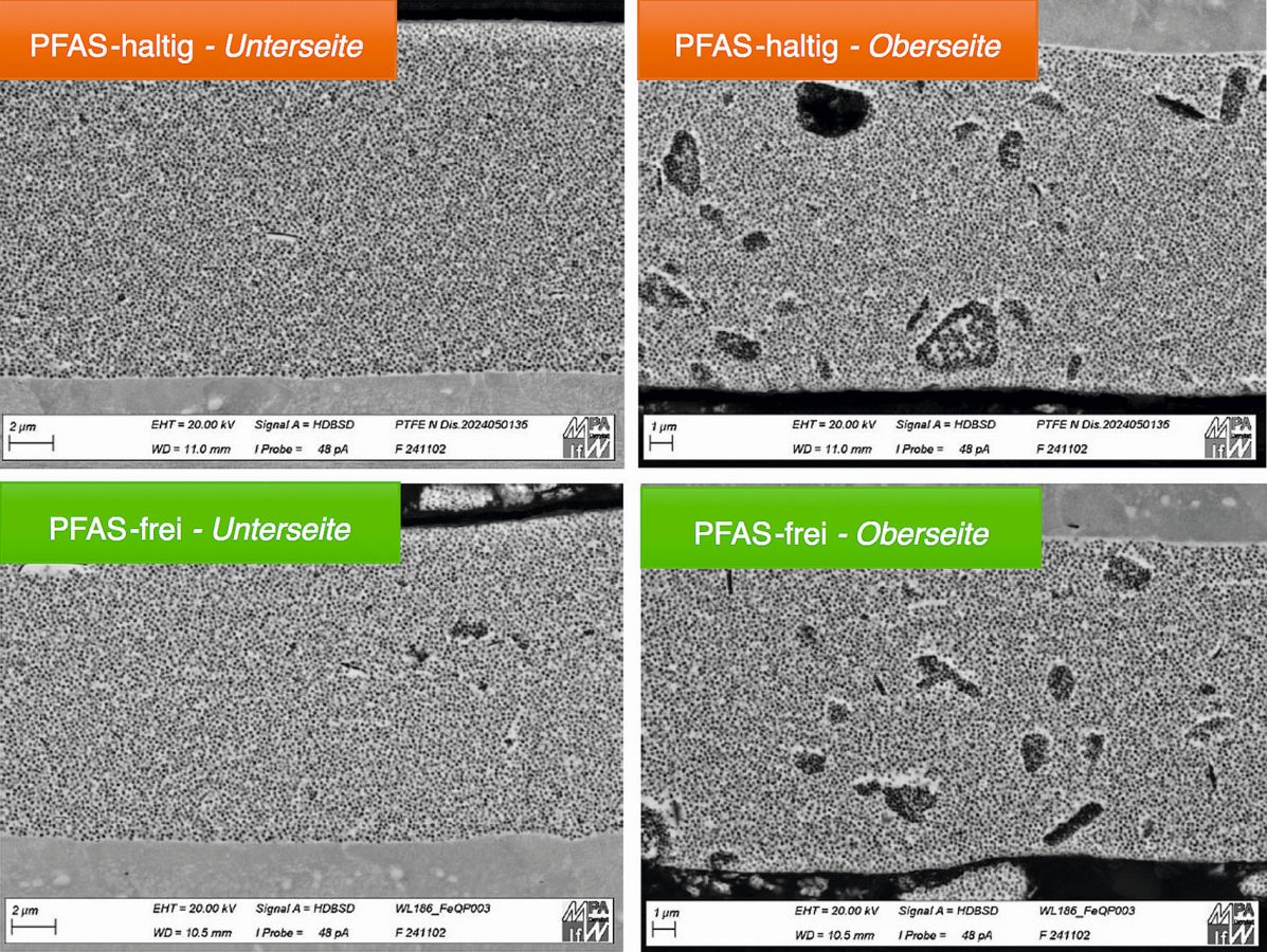
Electroless deposited nickel-phosphorus (NiP) dispersion layers containing polytetrafluoroethylene (PTFE) are used due to their low coefficient of friction and low surface energy to minimize the sliding friction of surfaces and, for example, to improve demouldability in tools. These coatings are deposited from electroless nickel electrolytes that contain PTFE in the form of a dispersion. This consists not only of PTFE particles, but also contains surfactant systems to stabilize the dispersion during production, storage and application. The PTFE-Durni-Disp C described here contains no PFAS surfactants and also has optimized process and coating properties.
Fluorosurfactants belong to the class of per- and polyfluorinated alkyl compounds (PFAS [1]). This substance class is characterized by a high chemical and thermal stability and thus a high persistence (long-term stability). It therefore poses a risk to living organisms and the environment and the European Chemicals Agency (ECHA) is currently examining a draft ban for this substance class. Regardless of the pending test result, the PTFE-Durni-Disp N process has been further developed. The new process is called PTFE-Durni-Disp C and does not contain any PFAS surfactants. It also has optimized process and coating properties.
Requirements for the PTFE dispersion
The deposition of NiP dispersion layers is one of the autocatalytic coating processes. They contain sodium phosphinate (sodium hypophosphite) as a reducing agent and do not require an external power source. As this is a purely chemical reaction, the deposition is largely determined by the process parameters and the composition of the electrolyte. Both must be carefully monitored. Most processes operate at relatively high temperatures ( > 85 °C) and a pH value between 4 and 5. The requirement profile of a PTFE dispersion to be used in a PTFE-NiP process is very complex. In order for this to be fulfilled, the new PFAS-free surfactant system as a whole must have the following functional properties.
Dispersibility
The production of the PTFE dispersion is a complex multi-stage process that does not work without a suitable surfactant system. The PFAS-free surfactant system must be compatible with this process.
Storage stability
Like most multiphase systems, PTFE dispersion has a tendency to phase separation through sedimentation. To prevent this sedimentation during storage, the dispersion is stored rotating (in overhead mixers) and cooled in PE containers.
Stability in the NiP electrolyte
The PTFE dispersion is a non-polar organic medium and is added to a highly polar, salt-rich electrolyte during application. It must be homogeneously distributed in the electrolyte and must not flocculate at operating temperature (85 °C). Homogeneity must be maintained throughout the entire service life of the electrolyte.
Incorporation of the PTFE particles into the coating
The most important functional property from the user's point of view is the incorporation of the PTFE particles into the NiP matrix during coating. The so-called incorporation rate indicates the PTFE content in the NiP matrix either as a percentage (m/m) or as a percentage (V/V). Most surfactants impair the incorporation of the PTFE particles into the matrix.
Adhesive strength of the deposited layers
Certain surfactants reduce the adhesive strength of the deposited layers. Mechanical stress causes delamination and thus failure of the coating.
Fluorosurfactants are best suited to meet the above requirements. In order to provide the same functionality with fluorine-free surfactant systems, complex, carefully coordinated surfactant systems are required. Such a surfactant system was developed for the new PTFE-Durni-Disp C process and the process control was optimized at the same time. The process and coating properties of the new process are described below and compared with the previous version.
Methods used
Determination of the coating properties
Chemical composition of the coating
The composition of the layers is determined by means of chemical analysis. For this purpose, the dispersion layer is removed with nitric acid and the resulting solution is centrifuged. The supernatant solution is carefully removed and, after suitable dilution, prepared for analysis of the components of the coating matrix using ICP-OES (Agilent 5900 ICP-OES).
The residue containing the PTFE is dried and then weighed. The values obtained are used to calculate the composition of the coating as a percentage (m/m). The densities of the coating components can also be converted into percent (V/V). Any layer combinations or intermediate layers for adhesion promotion, such as Strike-Ni, are also removed and must be taken into account in the calculations.
Microhardness according to Knoop and Vickers
The microhardness test is carried out on metallographic cross-sections according to Knoop based on EN ISO 4545-1:2023 and according to Vickers based on EN ISO 6507-2:2018 using the Qness 60 A+ hardness tester from ATM. The fundamental problem with hardness tests on the cross-section is that the specifications stated in the standards for the distance between the hardness indentation and the coating edges cannot be met due to the low coating thicknesses of between 10 and 15 µm. Exemplary hardness impressions of both methods are shown in Figure 1. The test force used was 0.01 N for Vickers and 0.025 N for the Knoop method.
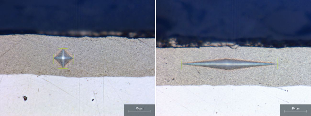 Fig. 1: Hardness indentations according to Vickers (left) and Knoop (right)
Sliding properties
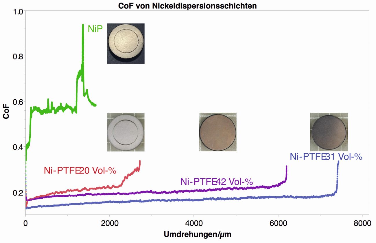
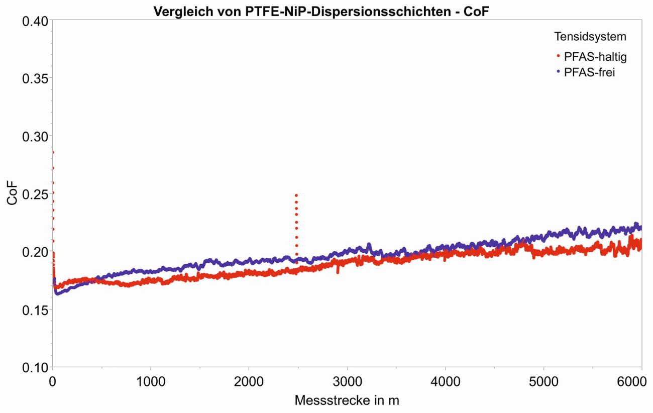
The coefficient of friction is determined in accordance with ASTM G99 using a CSM tribometer TRB from Anton Paar. The device determines the coefficient of friction as a function of the distance traveled on a rotating disk. The measurement parameters are listed in Table 1. When comparing the friction coefficient curves of different components up to the final failure of the coating, the influence of the coating thickness must be eliminated. This is achieved by dividing the number of revolutions traveled by the coating thickness (Fig. 2). This is not necessary when comparing an exclusively specified distance (Fig. 3).
|
Parameter |
Value |
|
Counter body / medium |
Ball 6 mm, material 100Cr6 G28 / air |
|
Radius |
10 mm |
|
Linear speed |
10 cm/sec |
|
Test load |
5 N |
|
Ambient conditions T / rel. humidity |
20 to 32 °C / 25 to 50% |
Contact angle measurement (non-stick properties)
The contact angle was determined using the MobileDrop GH11 from KRÜSS GmbH.
Process monitoring
To ensure a constant quality of the deposited layers, the process must be run within narrow limits and carefully monitored. The nickel content of the electrolyte is determined complexometrically at regular intervals using murexide as an indicator. In automatic systems, the nickel content can also be monitored inline photometrically. Phosphinate is determined iodometrically. For this purpose, the sample is mixed with iodide/iodate solution and hydrochloric acid and retitrated with sodium thiosulphate after standing in the dark for 30 minutes. Lead is used as a stabilizer and can be determined voltammetrically. The pH value is monitored potentiometrically using standard pH electrodes. It should be noted that both surfactants and PTFE (coating formation) influence the measurement. The PTFE content in the electrolyte and thus also the dispersion content can be determined by centrifuging an exact volume of electrolyte. The supernatant phase can be discarded or used to determine the other process parameters. The residue is dried and weighed and the dispersion content is then calculated in g/L.
Process characteristics of the method
The basic process parameters of the PTFE-Durni-Disp C process do not differ from those of the precursor process (Table 2). The process conversion to the PFAS-free variant is therefore easily possible. An important parameter is the deposition rate of a process. As the deposition process is an interfacial reaction and surfactants are "interfacially active", they can change the deposition behavior of an electrolyte: The PFAS-free surfactant system leads to a significantly higher deposition rate, which means that the process contributes to an increase in productivity (Tab. 3).
|
Deposition conditions |
|
|
Working temperature |
85 ± 1 °C |
|
pH value |
5.0 ± 0.1 (measured at 85 °C) |
|
Nickel content |
5.0 g/L (4.3 - 5.2 g/L) |
|
Reducing agent |
20 g/L (16 - 21 g/L) |
|
PTFE content |
6.0 g/L |
|
Stabilizer |
0.3 mg/L (0.2 - 0.7 mg/L) |
|
Bath load |
max. 0.8 dm2/l |
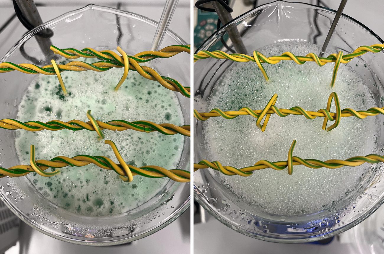
In dispersion processes, the distribution of the dispersion in the electrolyte is an important criterion. This is where the two process variants differ (Fig. 4). While deposits in the foam on the electrolyte surface are recognizable in the conventional process (once formed, large agglomerates are lost to the coating process, i.e. the effective PTFE content in the electrolyte decreases), this phenomenon does not occur with the new PTFE-Durni-Disp C variant. In principle, agglomerate formation also takes place in the electrolyte in all dispersion processes, the extent of which depends on numerous factors. The higher settling speed of larger particles leads to the formation of agglomerates on upwardly oriented component surfaces when coating without corresponding component movement (Fig. 5). There is no significant difference here between the conventional N and the new C variant.
Process control
NiP electrolytes are usually prepared with two concentrates, a buffer and deionized water and then the pH value is adjusted to just below the target value at room temperature. The same procedure is used for the PTFE-Durni-Disp N and C processes and the dispersion is then added. After heating to operating temperature and adjusting the pH value, the electrolyte is ready for use. With the old N version, approx. 25 mL/L ammonia, 25 % (m/m) is required to adjust the pH value, which results in a not inconsiderable odor nuisance for the employees. As part of the development of the new surfactant system, the process chemistry of the new C variant was also adjusted so that the preparation is already close to the target pH value without the addition of buffer and ammonia.
The new surfactant system is also adjusted so that surfactants no longer need to be added during the bath journey. Only the nickel source (Replenisher 1), the reducing agent (Replenisher 2), the PTFE dispersion and ammonia for pH regulation are required for process control.
Layer properties
The composition of the deposited coatings can be determined using the method described in the chapter "Chemical composition of the coating". The concentration range of the individual components is listed in Table 3. The PTFE content of a coating can also be roughly determined by the color shade - lighter coatings contain less PTFE compared to darker coatings.
|
Parameters |
PTFE N (PFAS-containing) |
PTFE C (PFAS-free) |
|
PTFE installation rate in % (V/V) |
20 - 40 |
30 - 40 |
|
P content of the matrix in % (m/m) |
9 - 10 |
9.5 - 10.5 |
|
Hardness (HV0.01) |
200 - 240 |
200 - 240 |
|
Hardness (HK0.025) |
170 - 230 |
170 - 230 |
|
Coefficient of friction |
0.1 - 0,3 |
0.1 - 0.3 |
|
Separation rate in µm/h |
7 - 8 |
9 - 10 |
Sliding properties
The most important layer property of the NiP-PTFE dispersion layer is undoubtedly the low coefficient of friction (CoF). Figure 2 shows the course of the CoF in the ball-on-disc tribometer test for different PTFE contents in the deposited layers. The x-axis is the number of revolutions per µm layer in order to eliminate the influence of the layer thickness.
As expected, the CoF for NiP coatings without PTFE rises quickly to 0.4 and then to 0.6. With a PTFE content of 20 % (V/V), the CoF drops drastically to 0.2 to 0.25, but increases after about 2500 revolutions per µm. With a PTFE content of around 30 % (V/V) in the coating, the CoF is significantly lower and the failure of the coating only begins after around 7500 revolutions per µm. If the PTFE content is further increased to 42 % (V/V) in the coating, the CoF increases and the service life is slightly reduced again. This behavior can be explained by the very high point load in the ball-on-disc test and the lack of support provided by the nickel matrix of the overall softer coating.
The curves for the friction coefficients of the PFAS-containing N variant and the PFAS-free C variant are compared in Figure 3. With the same PTFE content in the coating, no significant differences in the friction coefficient curves can be seen.
Non-stick properties
![Abb. 6: Der Kontaktwinkel als Maß für die Antihaftwirkung einer NiP-PTFE-Schicht. Der rote Balken repräsentiert eine reine NiP-Schicht, der rechte Balken eine PTFE-Oberfläche [2] Abb. 6: Der Kontaktwinkel als Maß für die Antihaftwirkung einer NiP-PTFE-Schicht. Der rote Balken repräsentiert eine reine NiP-Schicht, der rechte Balken eine PTFE-Oberfläche [2]](/images/stories/Abo-2025-08/gt-2025-08-44.jpg) Fig. 6: The contact angle as a measure of the non-stick effect of a NiP-PTFE coating. The red bar represents a pure NiP layer, the right bar a PTFE surface [2]In addition to the coefficient of friction (CoF), the non-stick effect of NiP-PTFE layers (keyword: demoldability) is of great importance. The non-stick effect depends on the interfacial energy. One measure of this is the contact angle that forms when a surface is wetted with a drop of liquid (in this case deionized water). A larger contact angle indicates a lower adhesive effect of the surface and therefore better demoldability. As expected, the measured contact angles for the NiP-PTFE layers (green) lie between the values for the pure NiP layer (red) and PTFE (blue), Figure 6. The comparatively lower contact angle of the NiP-PTFE layer at 42 % (V/V) is due to the roughness and topography of the layer properties, which are influenced by the high PTFE content.
Fig. 6: The contact angle as a measure of the non-stick effect of a NiP-PTFE coating. The red bar represents a pure NiP layer, the right bar a PTFE surface [2]In addition to the coefficient of friction (CoF), the non-stick effect of NiP-PTFE layers (keyword: demoldability) is of great importance. The non-stick effect depends on the interfacial energy. One measure of this is the contact angle that forms when a surface is wetted with a drop of liquid (in this case deionized water). A larger contact angle indicates a lower adhesive effect of the surface and therefore better demoldability. As expected, the measured contact angles for the NiP-PTFE layers (green) lie between the values for the pure NiP layer (red) and PTFE (blue), Figure 6. The comparatively lower contact angle of the NiP-PTFE layer at 42 % (V/V) is due to the roughness and topography of the layer properties, which are influenced by the high PTFE content.
The coating hardness of NiP-PTFE coatings is significantly lower than that of pure NiP coatings due to the PTFE content in the coating. The measured values correlate with the PTFE content in the coating, but the measured values are only for orientation purposes.
Table 3 compares the most important coating properties of the two process variants.
Conclusion and outlook
To produce friction-reducing electroless nickel coatings, PTFE is used in the form of dispersions in the electrolytes, which are stabilized with the aid of fluorine surfactants. However, these surfactants are facing a possible restriction or ban as a result of the proposal by the European Chemicals Agency (ECHA) under Regulation "ECHA/NR/23/01", as they are classed as controversial PFAS compounds. Intensive development work has resulted in a modified and improved process for the deposition of nickel dispersion layers with PTFE particles without the use of fluorosurfactants (PFAS compounds). The resulting coatings are characterized by a particularly low coefficient of friction, excellent non-stick properties and a uniform coating thickness distribution, as is known from chemically deposited nickel coatings. Thanks to the even distribution of the PTFE particles, dry lubrication is maintained even as the coating wears, which increases its durability and versatility in various applications. The service life of the coatings depends largely on the coating thickness, the PTFE content and the hardness of the coating, whereby the requirements vary depending on the area of application.
Independently of the further results and measures taken by the ECHA, an alternative process is now available that does not use fluorosurfactants. In order to be able to meet possible further challenges in the context of the impending PFAS restrictions, further work will be carried out on the basis of the findings on PFAS-free surfactants in the search for adequate alternatives to PTFE itself.
Literature
[1] Wikipedia: Per- and polyfluorinated alkyl compounds. www.wikipedia.de retrieved on 08.07.2025
[2] Tharwat F. Tadros: Dispersion of Powders in Liquids and Stabilization of Suspensions, Wiley VCH, Weinheim, 2012, p. 18.

