The use of contact lubricants is state of the art for current-carrying plug connections in electrical power engineering. As an alternative to this, self-lubricating dispersion layers were to be electroplated and subsequently characterized. As part of the work, it was possible to incorporate various particles known as solid lubricants (graphite, hBN, MoS2, WS2, Bi2S3 and SnS) into a silver matrix. Ag-graphite was used as a reference system to assess the friction and wear behavior of the other particles. While coatings with hBN, Bi2S3 and SnS did not show any tribological improvement compared to pure silver, coatings in which WS2 and MoS2 were incorporated showed promising tribological properties.
1 Introduction
Due to the energy transition and the electrification of individual transportation, the reliable transport of electrical energy is increasingly becoming the focus of society. A reliable power grid in which all components can be operated with long-term stability over decades is essential for this. A great deal of attention is being paid to current-carrying connectors, in which the electrical current is transferred from one conductor to another. The current state of the art is a coating of the contact partners with subsequent application of a contact lubricant. This allows a high number of mating cycles to be achieved during operation and ensures the safety and reliability of the component. However, this is associated with certain challenges. Precise dosing of the contact lubricant is essential to keep the contact resistance as low as possible. In addition, the contact lubricant must be stable over the long term and temperature-resistant, which is why ecologically questionable materials based on fluorochemicals are often used. As an alternative to conventional plug contacts treated with contact lubricant, electroplated silver dispersion coatings are being investigated in this work. By incorporating self-lubricating particles in silver layers, it should be possible to dispense with the use of an additional contact lubricant. The galvanic production of dispersion layers by means of simultaneous particle deposition has been known for decades [1]. The properties of the coatings can be specifically influenced by varying the electrolyte and process parameters [2]. Depending on the deposited particle type and installation rate, improvements in abrasion and wear resistance, sliding properties, strength, ductility and corrosion resistance can be achieved. The suitability of silver-graphite dispersion layers for self-lubricating electrical contacts is already known [3-7], which is why this system is to serve as a reference system in this work. As an alternative to graphite, other solid lubricants in particle form are to be incorporated into silver coatings and their properties investigated. The positive influence on the friction and wear properties through the incorporation of various solid lubricants such as hBN or metal sulphides in nickel coatings is shown in [8-13]. The aim of the work presented here is to examine the extent to which these findings can be transferred to silver as a matrix metal. The higher chemical and thermal resistance of hBN compared to graphite could result in advantages, for example with regard to the stress tolerances of the components.
The work presented was carried out as part of the BMWi-funded research project "Contact and long-term behavior of self-lubricating coatings in current-carrying connections in electrical power engineering" (BMWi_03EI6011C) with the participation of fem (Research Institute for Precious Metals + Metal Chemistry), the IEEH (Institute for Electrical Power Supply and High Voltage Technology) at TU Dresden and several industrial partners. In this project, fem's task is to deposit various dispersoids as homogeneously and agglomerate-free as possible in a silver matrix by means of electrodeposition. Different hBN particle variants, various metal sulphides (WS2, MoS2, Bi2S3 and SnS) and graphite as a reference system are used as dispersoids. At the beginning, a comprehensive tribological and electrical characterization of the different systems is carried out on planar model geometries before industrial test specimens are produced and characterized under real stress conditions in the course of the project.
The present work concentrates on the electrodeposition of the dispersion layers on model geometries as well as on the associated material and tribological characterizations carried out on the fem.
2 Experimental aspects
2.1 Materials and process parameters Substrates and intermediate layers
Two different substrate types were used for the electrodeposition of the silver dispersion layers. Unsupported films were produced for the material characterization of the samples. A stainless steel sheet was used for this purpose, from which the films could be mechanically removed after coating. Planar carrier substrates were required for the tribological tests, for which 3 mm thick brass sheets were used, which were pre-copper-plated and pre-silver-plated with cyanide (Tab. 1).
| Sample type | Sample type | |
|
Free-standing film |
Coating on substrate | |
| Characterization |
installation rate, film thickness, homogeneity |
tribotest |
| substrate | Stainless steel | brass |
| Pre-treatment |
Degreasing Decapping |
Degreasing Decapping |
| Intermediate layers | Pre-silver |
Copper Pre-silver |
| Coating thickness | 20-30 µm | 6 µm |
Electrolytes and wetting agents
An additive-free cyanide silver electrolyte (in-house preparation) was used as standard for the deposition of the silver dispersion layers. For comparison purposes, individual depositions were carried out using a commercial, cyanide-free alkaline silver electrolyte. The wetting agent and particle concentrations were adjusted individually for the different dispersoids (see Chapter 3) and Table 2.
A surfactant known from Ag-graphite dispersion deposition was used as the standard wetting agent. This is a commercially available, anion-active wetting agent with a chain length < C 10. This wetting agent was used for all particle types. In addition, the following other non-ionic surfactants were tested as possible alternatives for separation tests with hBN particles:
- Lutensol AT-25 (BASF), fatty alcohol ethoxylate
- Lugalvan G35 (BASF), polyethyleneimine
- Tamol NN 8906 or 8401 (BASF / BTC), naphthyl sulfone polymer
- Triton X200 (Sigmaaldrich), alkylphenylpolyethylene glycol
Particles
The particles used in this study are listed in Table 3.
Gerullis et al. showed in the case of the matrix metal nickel that the incorporation and tribological properties of nickel-hBN dispersion layers can be improved by plasma modification of hBN particles [16]. For this reason, plasma-treated variants of the 3.5 µm hBN particles were also investigated (O2 plasma and O2 /Ar plasma).
| Electrolyte | Trade name | Manufacturer |
Current density, A/dm2 |
Temperature, °C |
|
Ag cyanidic additive-free |
- | Own approach | 1,0 (0,75-1,5) | RT |
|
Ag alkaline cyanide-free |
Heliofab Ag 340 |
MacDermid Enthone |
1,0 | 50 |
| Particle type |
Trade name |
Manufacturer |
Particle size D50 [µm] |
Particle concentration in the electrolyte, g/l |
| Graphite | UF2 99.5 | AMG Graphite | 4,5 | 120-160 |
| hBN | HeBoFill® BL-SP 035 | Henze BNP AG | 3,5 | 50-100 |
| hBN | HeBoFill® LL SP 010 | 1,0 | 50-100 | |
| WS2 | Tribotecc® - WS 2 | Tribotecc GmbH | 3,0 | 1-20 |
| MoS2 | Tribotecc® - MOS XF | 8,5 | 1-20 | |
| Bi2S3 | Tribotecc® - BIS 84 | 2,0 | 5 | |
| SnS | Tribotecc® - SNS 2 | 3,0 | 5 |
Container geometry, particle circulation
A separator vessel optimized for dispersion separation was used for the tests, the geometry of which prevents the particles from settling during separation. The particles were circulated using a magnetic stirrer (stirring speed 200-600 rpm), sometimes additionally supported by a dispersing rod. In addition to the agitation, the latter ensures that the agglomerates are broken up mechanically (Fig. 1).
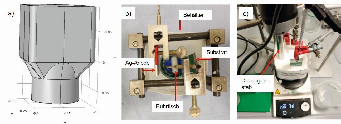 Fig. 1: Separation vessel for dispersion separation; a) side view of vessel (drawing), b) top view of vessel with magnetic stirrer (photo), c) side view with dispersing rod (photo)
Pulse plating
The dispersion layers were usually deposited under direct current conditions. For the Ag-graphite and Ag-hBN systems, the influence of pulse plating conditions on the installation rate was also investigated. The pulse parameters were set according to the specifications in [14]. Several variants, including reverse pulse plating, were investigated for Ag-graphite (Table 4).
| Parameters | Variant A | Variant B | Variant C | Variant D |
|
Pulse current density, A/dm2 |
5,0 | 5,0 | 10,0 | 3,1 |
|
Reverse pulse current density, A/dm2 |
- | - | - | 5,0 |
| Pulse duration, ms | 1 | 5 | 5 | 2 |
| Reverse pulse duration, ms | - | - | - | 0,4 |
| Pulse pause, ms | 10 | 95 | 95 | 10 |
The parameters investigated for the Ag-hBN system are summarized in Table 5.
| Parameters | Variant A | Variant B | Variant C | Variant D |
|
Pulse current density, A/dm2 |
20 | 20 | 20 | 40 |
|
Average current density, A/dm2 |
1 | 2 | 1 | 2 |
| Pulse duration, ms | 1 | 1 | 5 | 1 |
| Pulse pause, ms | 19 | 9 | 95 | 19 |
The influence of the pulse parameters on particle incorporation can be different for each system and must therefore be determined individually. Depending on the interaction between the particles and the cathode surface, it may also be the case that the particles are washed off the surface during the pulse pauses and pulse deposition can have a negative effect on the installation rate [15].
2.2 Characterization of the material
To assess the homogeneity of the particle incorporation, the particle content by means of gray value measurements and the layer thickness profile of the dispersion films, cross-sections of the different samples were produced and then examined microscopically. At the same time, the particle content of the films (with the exception of hBN) was quantified by combustion analysis. For a detailed analysis, selected samples as well as particles and friction marks were examined using scanning electron microscopy (Gemini SEM 300 from Zeiss).
2.3 Tribological characterization
The tribological tests were carried out as a pin-on-disk test using a "CSEM Pin On Disk Tester" tribometer under constant climatic conditions at 23 °C and 50 % relative humidity.
A firmly clamped 100Cr6 ball coated with approx. 20 µm pure silver with a diameter of 6 mm was used as a counter body. The friction track diameter was 2 mm in each case, the speed was 500 rpm, which resulted in a sliding speed of 52.4 mm/s. The normal force was 1 N in each case. The normal force was 1 N in each case. 1000 revolutions were completed per sample and test. This resulted in a friction path of 6.28 m on the counter body (ball). During the pin-on-disk test, the course of the coefficient of friction µ was recorded in situ. The average coefficient of friction µ was also calculated over the entire 1000 revolutions to summarize the evaluation of the individual layers. In addition, various microscopic examinations were carried out on the samples and mating specimens to evaluate the tribological properties (see section 3.1).
3 Results
3.1 Material characterization of the Ag-graphite dispersion layers
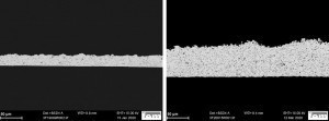 Fig. 2: Cross-sectional micrographs of Ag-graphite dispersion layers deposited with a) direct current 0.8 A/dm2 , 120 g/l graphite, incorporation rate 6.6 vol.% and b) pulse current (reverse pulse plating), 160 g/l graphite, incorporation rate 9.5 vol.%Forthe Ag-graphite reference system, incorporation rates between 5-10 vol.% graphite were aimed for in order to guarantee the required tribological properties. Figure 2 shows the cross-section of a sample prepared with the following parameters: cyanide electrolyte, 3 g/l standard wetting agent, 120 g/l graphite, current density 0.8 A/dm2, time 60 min, circulation: magnetic stirrer 500 rpm. The particles are deposited homogeneously distributed with an incorporation rate of approx. 6.7 % by volume. By increasing the particle concentration to 160 g/l, the graphite incorporation can be further increased to approx. 8.5 vol.%, whereby the deposited films then become increasingly porous. By depositing under reverse pulse plating conditions, as shown in Figure 2, the incorporation rate could be increased to 9.5% by volume. At the same time, finer particles seem to be preferentially incorporated.
Ag-hBN
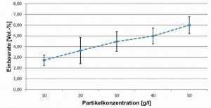
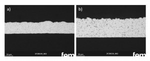
The first step was to determine the influence of the hBN particle concentration in the electrolyte on the incorporation rate into the coating. For this purpose, the hBN concentration was gradually increased from 10 g/l to 70 g/l, with depositions being carried out at each concentration. The wetting agent concentration was adjusted in each case, i.e. when the particle concentration was increased, the wetting agent was added first in a defined quantity. Figure 3 shows the dependence of the installation rate on the particle concentration in the electrolyte. From an electrolyte with 50 g/l hBN, layers with up to 6 vol.% hBN can be deposited without further optimization measures. In this case, the particles were only circulated using a magnetic stirrer, which is why no uniform layers were obtained in the depositions with higher concentrations (60 g/l and 70 g/l). By additionally using a dispersing rod, the particle concentrations can be increased up to 100 g/l without impairing the homogeneity of the layer thicknesses. Figure 4 shows SEM cross-sectional images of Ag-hBN layers, a) for a particle size of 1 µm and b) for a particle size of 3.5 µm with optimized deposition conditions in each case.
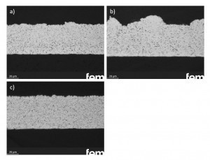 Fig. 5: Ag-hBN dispersion layers (d50 = 3.5 µm) with a) cyanide electrolyte and wetting agent Lutensol At-25, b) Heliofab electrolyte and standard wetting agent and c) cyanide electrolyte without wetting agent, plasma-modified hBN particlesThesample in Figure 4a) with the 1 µm hBN particles was deposited at 1 A/dm2 and a particle concentration of 50 g/l, resulting in an incorporation rate of 9 vol.% was achieved. Significantly higher particle concentrations (100 g/l) had to be selected for the depositions with larger particles in order to achieve comparable incorporation rates. By simultaneously lowering the electrolyte temperature to 0 °C, the incorporation rate could be increased to 7.3 % by volume. Regardless of the wetting agent and the electrolyte system, the hBN particles could be homogeneously incorporated into the Ag layers. The following variants are shown as examples in Figure 5: a) cyanide electrolyte, wetting agent Lutensol AT-25, b) Heliofab electrolyte, standard wetting agent, c) Heliofab electrolyte, without wetting agent, Ar/O2 plasma modified hBN particles. All three samples were deposited with a particle concentration of 120 g/l and at 1 A/dm2.
The depositions under pulse plating conditions were carried out at RT using a dispersing rod. The particle concentration was 50 g/l. Similar to direct current deposition, a homogeneous distribution of the particles is also achieved under pulse current, but the roughness of the surface is reduced with pulse current. However, the incorporation rates cannot be increased; these are between 3.1-5.0 % by volume, depending on the parameters selected. A comparable sample under direct current conditions is approx. 6.0 % by volume.
Ag metal sulphide (MoS2, WS2, Bi2S3, SnS)
As with graphite and hBN, various sulphide particles were examined for their ability to be incorporated into silver coatings: Molybdenum, tungsten, bismuth and tin sulphide (MoS2, WS2, Bi2S3, SnS). The silver metal sulphide layers were initially deposited under standard conditions. However, porous, non-uniform layers were obtained by circulation using only a magnetic stirrer. The additional use of the dispersing rod resulted in a significant reduction in the porosity of the samples and a much more homogeneous deposition. The optimum particle concentration in the electrolyte had to be adjusted individually for each metal sulphide. In general, lower concentrations in the range up to a maximum of 20 g/l are more favorable for the metal sulfides compared to graphite and hBN, as higher particle contents result in increasing coating and thus blocking of the surface. In the case of WS2 and MoS2, the best results were achieved with a particle concentration of 10 g/l in the electrolyte; for the depositions with Bi2S3 and SnS, this was reduced to 5 g/l. Figure 6 shows cross-sections of dispersion layers with the different metal sulphides: a) Ag-WS2, b) Ag-MoS2, c) Ag-Bi2S3 and d) Ag-SnS. The achievable particle incorporation rate is lower for the metal sulphides than for graphite or hBN, in the range of approx. 3-5% by volume. These values were determined on the basis of the combustion analysis and therefore represent an integral value. As the majority of the particles are located on the surface, the actual incorporation rate into the coating is lower. The coating quality and the homogeneity of the particle incorporation are also poorer. Due to the significantly more porous layers, the particles often become embedded in the structure (see Fig. 6c) ). In addition, the process is very susceptible to changes in the process variables (e.g. electrode positioning, hydrodynamics, electrode size and geometry), which makes exact reproducibility difficult.
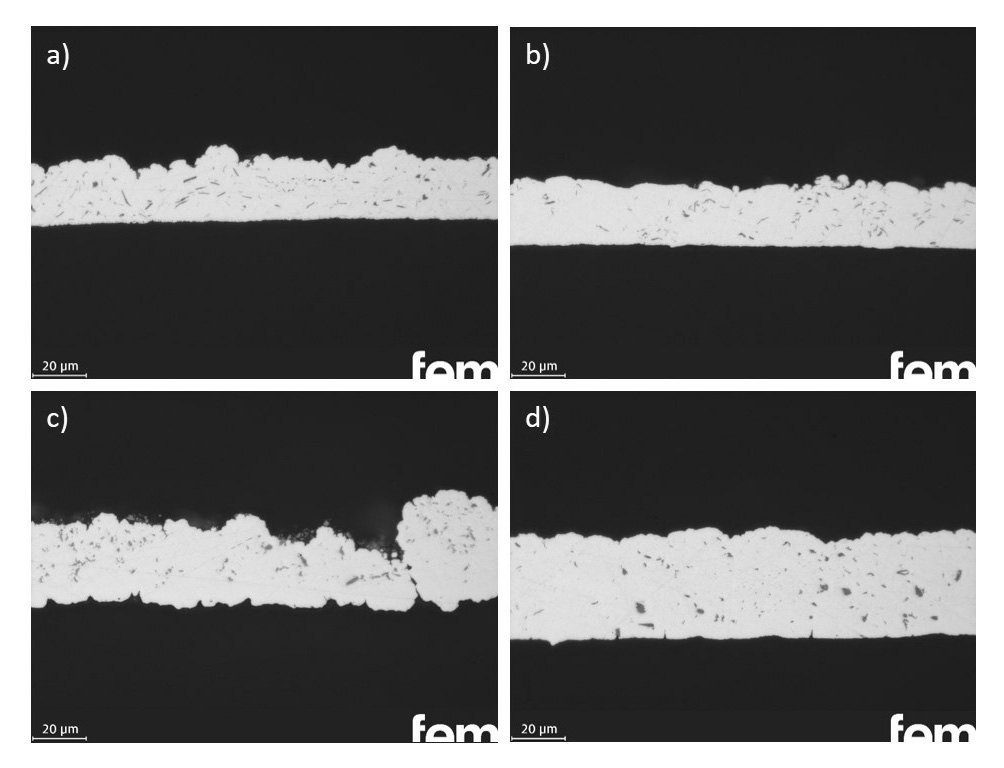 Fig. 6: Cross-sectional micrographs of Ag dispersion layers with a) WS2, b) MoS2, c) Bi2S3 and d) SnS particles
3.2 Tribological investigations Mean coefficient of friction
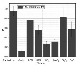 Fig. 7: Mean friction coefficients of a) pure silver and Ag dispersion layers with b) graphite, c) hBN, d) plasma-treated hBN, e) WS2, f) MoS2, g) Bi2S3 and h) SnS particlesFig. 7 shows the mean friction coefficients of pure silver and various Ag dispersion layers. The friction coefficients of a pure silver coating and an Ag-graphite coating determined under the respective test conditions serve as a reference. The incorporation of hBN particles does not significantly reduce the coefficient of friction compared to silver, regardless of the selected variant (electrolyte, wetting agent, pre-treatment of the particles, etc.). The same applies to the sulphides Bi2S3 and SnS. A significant reduction in the coefficient of friction compared to pure silver coatings is achieved by incorporating graphite (reference), WS2 or MoS2. By optimizing the process parameters, it was possible to achieve friction coefficients in the range of 0.3 and lower for the Ag-WS2 and Ag-MoS2 systems. Further work is still required, particularly with regard to the process reliability and reproducibility of the coating process.
Characterization of the friction track
Some of the samples were characterized before and after the tribotests (silver-plated 100Cr6 counterpart) using various methods:
- Light microscopy (optical visualization of the friction track)
- Confocal microscopy (3D representation of the friction track, average friction track depth, wear volume)
- Scanning electron microscopy SEM.
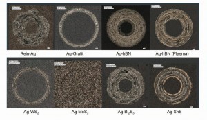
The light microscopic representation of the friction tracks in Figure 8 shows that the graphite, WS2 and MoS2-containing layers only have narrow friction tracks, whereas the other systems and pure silver have very large, flat friction tracks. The different friction track widths are based on different wear of the silver-plated counter body (ball) or on different, dominant wear mechanisms. While the counter-bodies of the coatings containing graphite, WS2 and MoS2 only exhibit comparatively low, predominantly abrasive wear and therefore only relatively small contact areas with the sample, the other coatings exhibit large-area counter-body wear characterized by adhesion, which in turn leads to the wide friction marks observed.
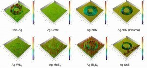
The three-dimensional confocal microscope images of the friction marks shown in Figure 9 confirm the visual impression gained in Figure 8. The graphite-containing layer obviously showed the least erosion, followed by the WS2-containing and MoS2-containing layers. In the latter case, the tribological investigation also resulted in a clear smoothing of the initially very rough surface. The extreme and apparently quite uniform wear of the two layers containing hBN and the layer containing SnS is also particularly striking in terms of the friction track depth. Here it appears as if the layers in the area of the friction track have been almost completely rubbed out. Although isolated peaks can be recognized in the friction tracks of these 3 systems, which indicate local, adhesive welding, there is practically no significant, smeared layer material at the edge of the friction track, as is the case with the pure silver layer.
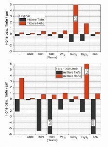
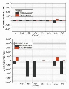
The data obtained using confocal microscopy was evaluated with regard to the average friction track depth and peak height (Fig. 10) as well as the generated wear volume (Fig. 11). As the basic topographies of the samples examined can also be taken into account within certain limits when determining the aforementioned parameters, the corresponding characteristic values were also determined on the respective original surfaces as reference values. For this purpose, exactly the same "measuring template" was used for each tested sample as for the respective friction track on the same sample.
With regard to both the friction track depth and the wear volume (trough volume), almost no difference can be seen between the condition before and after the measurement for the graphite-containing layer. This means that the wear generated in the friction track is so low that it is within the roughness of the initial surface. The layer containing WS2 has a slightly higher initial roughness, presumably caused by WS2 particles embedded in the area near the surface. During the friction test, these particles are obviously smeared, causing a slight ridge to form at the edge of the friction track, which results in a slight increase in the peak values (average height and peak volume) compared to the initial state. A slight but measurable wear can also be observed here due to a slight increase in the average friction track depth and the wear volume. Components of the displaced coating material may also have contributed to the formation of the wall at the edge of the friction track described above. A very high roughness, quantitatively described here by the "average height", is determined in the initial state of the MoS2-containing coating. Similar to the WS2-containing coating, this results from the MoS2 particles embedded in the surface, which to a certain extent protrude upwards from the surface. The characteristic values clearly show that this system results in a leveling of the initial topography in the area of the friction track. This can be seen both in the significantly reduced height and depth parameters after the tribotest and in the reduced trough and peak volumes compared to the initial state.
In the case of the two coatings containing hBN and the coating containing SnS, the friction track depth values, which for these 3 systems are in the range of the respective coating thicknesses applied to the samples, show that the coatings in the friction track area were almost completely removed during the 1000 revolutions. This confirms the impression already gained from the 3D representations of the friction tracks. These 3 systems also measured by far the highest wear volumes of all the coating systems investigated. In the case of the Bi2S3-containing coating, a clearly quantifiable wear can also be determined, the volume of which is roughly in the same range as that of the pure silver coating.
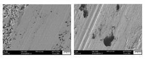
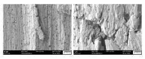
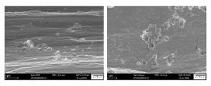
Figures 12 to 14 show the friction marks of an Ag-graphite and an Ag-hBN sample in the scanning electron microscope SEM.
While the graphite particles in Ag graphite appear to slide off in the friction track, this effect cannot be observed in hBN. Numerous loose particles were also localized outside the friction track. It is therefore currently assumed that the particles interact very little with the silver matrix and practically fall out of the layer as soon as they reach the surface. They would therefore not be available for a lubricating effect, but would rather contribute to the overall system not being able to withstand the effect of corresponding external forces due to the weak bond to the Ag matrix in conjunction with the installation rate of the hBN particles. This would be a possible explanation for the fact that the hBN particles not only do not lead to any improvement in the tribological properties, but that they even lead to the observed, significant deterioration in the wear properties compared to pure silver coatings.
4 Summary
As part of the work presented here, it was possible to incorporate various particles known as solid lubricants (graphite, hBN, WS2, MoS2, Bi2S3 and SnS) into a silver matrix. The process and electrolyte parameters were individually adapted and optimized for each system.
With graphite, very homogeneous and agglomerate-free dispersion layers could be deposited with graphite contents of up to 8.5 vol.% (DC) or 9.5 vol.% (reverse pulse). The particles (up to 160 g/l) were only circulated using a magnetic stirrer.
For hBN, relatively high particle concentrations could also be realized in the electrolyte; up to about 50 g/l only with magnetic stirrer or up to 100 g/l with additional circulation by a dispersing rod. Here too, particle incorporation is uniform and without agglomerates up to approx. 9 % by volume.
In the case of metal sulphides, the maximum particle concentrations in the electrolyte are significantly lower in the range up to approx. 20 g/l. Higher particle concentrations cause an increasing surface coating of the cathode, which ultimately leads to a complete blockage of the metal deposition. This phenomenon is very pronounced in the Bi2S3 and SnS systems. In addition, the particles adhere not only to the cathode, but to all other surfaces with which the electrolyte is in contact. Due to the lower maximum particle concentration in the electrolyte, the installation rates that can be achieved are correspondingly lower at approx. 3-4% by volume. It should be noted here that the surface is heavily coated with particles, which is why the actual incorporation rate into the silver matrix is even lower.
The tribological properties of Ag-graphite are excellent compared to pure silver. The average coefficient of friction is < 0.2 and the wear volume is extremely low. The coatings with WS2 and MoS2 show similar, albeit slightly poorer, tribological properties. In contrast, no notable improvement compared to pure silver is registered when hBN is incorporated. It is assumed that the particles fall out of the coating during exposure without being able to develop their (theoretical) lubricating effect. The interaction with the Ag matrix could also not be improved by surface modification of the particles such as plasma activation. The incorporation of the sulphides Bi2S3 and SnS also does not improve the tribological properties.
This means that, in addition to the known Ag-graphite system, only WS2 and MoS2 dispersion layers are tribologically convincing from the range of combinations investigated. Process reliability and reproducibility are to be further optimized in further investigations.
Acknowledgments:
The results presented were developed within the project "Self-lubricating coatings in current-carrying connections in electrical power engineering" funded by the Federal Ministry for Economic Affairs and Energy (BMWi) with the funding code BMWi 03EI6011. The authors would like to thank the BMWi for funding the joint project.
THE AUTHORS
B. Sc. Robin Arnet
Dipl.-Ing. (FH) Herbert Kappl
Dr. Ann-Kathrin Egetenmeyer
Dipl.-Ing.Heidi Willing
Literature
[1] Praktische Galvanotechnik: Ein Lehr- und Handbuch (4th ed.), 1988, 279, Eugen G. Leuze-Verlag KG.
[2] Meyer, J.; Sörgel, T.: Chemische und elektrochemische Dispersionsbeschichtung, WOMag, 2013 doi: 10.7395/2013/Soergel1
[3] Böhringer, G.; Laub, H.; Zjilstra, S.: Cyanide silver electrolyte for the electrodeposition of silver-graphite dispersion coatings, 1976, (DE2543082)
[4] Michelsen-Mohammadein, U.: Process for the application of silver-graphite dispersion coatings, 1991, (DE4010346)
[5] Tröger, L.; Damsch, S.: Contact Plating, 2014, (DE 102014119114)
[6] Lv, W.; Chen, T.S.; Zheng, K.Q.; Zhang, Z.G.: Feasible preparation and improved properties of Ag-graphite composite coating for switch contact by cyanide-free electrodeposition, Materials and Corrosion, 69(7), 2018, 933-940, https://doi.org/10.1002/maco.201709872
[7] Rehbein, P.; Haas, V.: Contact surfaces for electrical contacts, 2007, (US7638721)
[8] Tozar, A.; Karahan, D.H.: Effect of octylphenyl ether group nonionic surfactant on the electrodepositon of the hexagonal boron nitride reinforced Ni-B matrix composite coatings, Surface and Coatings Technology, 381, 2020, 125131, https://doi.org/10.1016/j.surfcoat.2019.125131
[9] Saini, R.; Roy, D.; Das, A.K.; Dixit, A.R.; Nayak, G.C.: Tribological behaviour and characterization of Ni-WS2 composite coating, International Journal of Surface Science and Engineering, 10(3), 2016, 240, https://doi.org/10.1504/ijsurfse.2016.076994
[10] He, Y.; Wang, S.; Sun, W.; Reed, P.; Walsh, F.: Synthesis and Properties of Electrodeposited Ni-Co/WS2 Nanocomposite Coatings, Coatings, 9(2), 2019, 148, https://doi.org/10.3390/coatings9020148
[11] Zhao, G.; Xue, Y.; Huang, Y.; Ye, Y.; Walsh, F.C.; Chen, J.; Wang, S.: One-step electrodeposition of a self-cleaning and corrosion resistant Ni/WS2superhydrophobic surface, RSC Advances, 6(64), 2016, 59104-59112, https://doi.org/10.1039/c6ra07899k
[12] Chen, Z.; Wagner, J.; Turq, V.; Hillairet, J.; Taberna, P.-L.; Laloo, R.; Duluard, S.; Bernard, J.-M.; Song, Y.; Yang, Q.; Lu, K.; Cheng, Y.: Surfactant-assisted electrodeposition of Au-Co/WS2 self-lubricating coating from WS2 suspended cyanide electrolyte, Journal of Alloys and Compounds, 829, 2020, 154585, https://doi.org/10.1016/j.jallcom.2020.154585
[13] Shi, L.; Sun, C.; Liu, W.: Electrodeposited nickel-cobalt composite coating containing MoS2, Applied Surface Science, 254(21), 2008, 6880-6885, https://doi.org/10.1016/j.apsusc.2008.04.089
[14] Nickchi, T.; Ghorbani, M.: Pulsed electrodeposition and characterization of bronze-graphite composite coatings, Surface and Coatings Technology, 203(20-21), 2009, 3037-3043, https://doi.org/10.1016/j.surfcoat.2009.03.029
[15] Puippe, J.C.; Leaman, F.: Pulse-Plating: Electrolytic Metal Deposition with Pulsed Current (1st ed.), 1990, Eugen G. Leuze-Verlag KG
[16] Gerullis, S.; Gerschütz, A.; Beier, O.; Pfuch, A.; Schmidt, J.; Grünler, B.: Modification of dry lubricating powders by atmospheric pressure plasma, 1, 2020, 112-121


