The Moon is the largest and brightest celestial object in the night sky. Being the only natural satellite of the Earth, it has been a centre of attention for mankind. Understanding the Moon may also provide us a pathway to unravel the early evolution of our solar system and that of Earth. Landing on the Moon still remains challenging. This is because …
- there is a communications delay between Earth and the Moon – the craft therefore has to land autonomously
- for a safe landing the speed of craft has to slowed down from thousands of km per hour to around 1 m per second by precisely firing of descent engines, and
- actual landing terrain is not known precisely.
India's second moon mission Chandrayaan-2 after successful orbital insertion, led to the Lander's crash-landing on September 6, 2019 due to last-minute software glitch in the guidance software [1]. Three other spacecrafts, Israeli Beresheet in April 2019, Japanese Hakuto-R in April 2023, and Russian Luna-25 in August 2023 have also crash-landed.
Why the Lunar South Pole?
The south pole zones of the Moon that remain in shadow are much larger than the north pole. There is a possibility of the presence of icy walls in the permanently shadowed areas. These cold traps craters in the south pole region may also contain a fossil record of the early solar system. That’s why the south pole is considered a big resource rich target. The south pole region is also a very difficult terrain with harsh conditions, including temperatures as low as -233 °C. Chandrayaan-3 lander soft landed near lunar south pole on the high plain between Manzinus-C and Simpelius-N craters.
Mission Objectives
Chandrayaan-3 had three main objectives:
- The primary objective was safe, precise soft landing of Lander closer to the lunar south pole
- To demonstrate Rover operations on the Moon surface
- To carry out on site scientific experiments on the lunar soil.
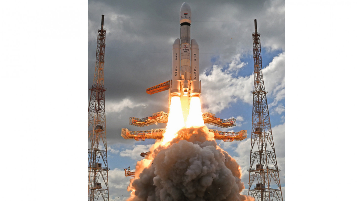
To achieve the above mission objectives, several advanced technologies were introduced in Chandrayann-3 including instrumentation redundancy, structural rigidity and multiple contingencies. Details on launch vehicle are presented in Figure 1 [2]. Fig. 1: Launch vehicle Mark-III-M4
The Spacecraft
Chandrayaan-3 composite spacecraft in a stacked configuration is shown in Figure 2. The propulsion module is at the bottom and the lander on the top with the rover inside. The major specifications of the spacecraft are as follows [2, 3]:
- Mission life: Propulsion module: 3–6 months, lander module: one lunar day (approx. 14 Earth days)
- Mass: Propulsion module: 2148 kg, lander module: 1752 kg including rover of 26 kg, total: 3900 kg
- Power generation: Propulsion module: 758 W, lander module: 738 W, winter solstice with bias; rover: 50 W
- Communication: Propulsion module communicates with Indian deep space network (IDSN). Whereas lander module communicates with both IDSN and Rover. Chandrayaan-2 orbiter is used as a back-up link. The rover can communicate only with lander.
 Fig. 2: Chandrayaan-3 integrated module
Propulsion Module (PM)
The propulsion module illustrated in Figure 3, is used as a relay satellite. It will remain in lunar orbit to enable communications with Earth. The main function of PM was to carry the lander module from parking Earth orbit to polar Lunar orbit. The propulsion module is a box-like structure with one large solar panel mounted on one side and a large cylinder on top (Inter modular adapter cone) that acts as a mounting structure for the Lander. It has a mass of 2148 kg, of which 1696 kg is propellant. Communications is via S-band and attitude sensors include a star sensor, sun sensor, inertial reference unit (IRU) and accelerometer package (IRAP). As a value addition, the PM also carried a scientific payload, spectro-polarimetry of habitable Planet Earth (SHAPE) to study the spectral and polarimetric measurements of Earth from lunar orbit. Fig. 3: Propulsion module
Lander-Vikram Module (LM)
The lander (Vikram named after Indian space program pioneer Vikram Sarabhai) is box-shaped with four landing legs (Figure 4). The four legs of the lander absorb energy when touched down on the Moon surface and provide stability to it for further operations. After landing on the Moon, the ramp opened and the rover descended to the lunar surface. The lander has side-mounted solar panels. Similar to Chandrayaan-2, Chandrayaan-3 Lander has four scientific payloads to perform experiments on the lunar surface:") Fig. 4: Lander module (Vikram)
Fig. 4: Lander module (Vikram)
Radio Anatomy of Moon Bound Hypersensitive ionosphere and Atmosphere (RAMBHA): The lunar ionosphere is a highly dynamic plasma environment. RAMBHA Langmuir Probe measures the near surface plasma (ions and electrons) density and its variation with time. The initial measurements indicate that the plasma encompassing the lunar surface is relatively sparse, characterized by a densitiy range of 5 to 30 million electrons per cubic meter throughout the lunar day.Chandra’s Surface Thermo-Physical Experiment (CHaSTE) is fitted with 10 individual temperature sensors that measures the vertical temperature gradient and thermal conductivity of the lunar topsoil. It is equipped with a controlled penetration mechanism capable of reaching a depth of 10 cm. Instrument for Lunar Seismic Activity (ILSA) is a triple axis, MEMS-based seismometer that can detect minute ground displacement, velocity, or acceleration caused by lunar quakes. Its primary objective is to characterize the seismicity around the landing site. ILSA comprises a cluster of six high-sensitivity accelerometers. The core sensing element consists of a spring-mass system with comb- structured electrodes. External vibrations lead to a deflection of the spring, resulting in a change in capacitance which is converted into voltage. The Laser Retroreflector Array (LRA) is employed as a passive experiment to understand the dynamics of Earth's Moon system. It will take precise measurements of distance between the reflector on the lunar surface and satellites in lunar orbit.
Rover-Pragyan
The Rover Pragyan (meaning "wisdom" in Sanskrit) is a mobile laboratory to traverse the lunar surface at the rate of 1 cm/ second, collect samples, and analyse their geological and chemical composition. It has navigation cameras, a solar panel that can generate 50 W, and can communicate with the Lander via Rx/Tx antennas. The expected operating time of the rover was one lunar day (14 Earth days) as its electronics were not designed to endure the frigid lunar night. Two aft wheels of the Rover are used to measure the exact distance travelled by visual odometry. The details are presented in Figure 5. Rover has two scientific instruments. The first instrument, the so-called Laser Induced Breakdown Spectroscope (LIBS) is designed to carry out elemental analysis near the landing site. A high-energy laser pulse is focused onto the surface of a rock or soil that generates an extremely hot and localized plasma. The collected plasma light is spectrally resolved and detected by Charge Coupled Device Detectors. Since each element emits a characteristic set of wavelengths of light in a plasma state, the elemental composition of the material is determined. The first in-situ close range LIBS spectrum of the lunar surface recorded on August 28, 2023 is presented in Figure 6. Analyses unveiled the presence of Al, S, Ca, Fe, Cr, Ti, Mn, Si, and O. It unambiguously confirms the presence of sulphur. Investigation on the presence of hydrogen is underway. The second instrument is a Alpha Particle X-ray Spectrometer (APXS) which determines the in-situ elemental composition by X-ray fluorescence spectroscopy. APXS can detect all major rock-forming elements. APXS onboard Rover deployed down to observe the lunar sample. APXS observed the presence of interesting minor elements, Al, Si, Ca, and Fe including S. Fig. 5: Pragyan rover
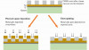
Role of Surface Modification in Chandrayaan-3
Surface modification is employed as an ideal means of improving one or more surface properties, chemical, mechanical, electrical or optical. It is used to prevent atmospheric corrosion; to increase micro hardness and reduce friction on sliding surfaces; to provide better adhesion for paints, lubricants and adhesives; to impart thermal/electrical resistance or conductance; to provide adequate optical surface for thermal control applications, etc. Finishing for space applications, however, requires higher standards and better control than those used for ground applications, because an on-orbit spacecraft is not approachable for repair and space conditions are severe [4]. Mass reduction is an important criterion in spacecraft design, because the cost of spacecraft launch is enormous. Most of the structural components of Chandrayaan-3 were made of light metal alloys, viz., aluminium, magnesium, or titanium. Electronic housings, and mechanism components were largely fabricated out of aluminium alloys. Titanium was used for heat shields and a variety of fasteners. Fig. 6: LIBS spectrum of lunar surface
- The spacecraft panels were made of lightweight composite honeycomb structure sandwiched with aluminium face sheets. The face sheets were chromated or chromic acid anodized for corrosion protection and for providing good bonding with adhesives inside and paints outside. The aluminium or magnesium inserts used in the panels were anodized.
- The sub-system parts made out of Al, Mg, or Ti were either anodized or microarc oxidized for corrosion protection, and/or improvement is adhesion of subsequent coatings.
- Hard anodizing on aluminium parts was used to improve the tribological properties of deployment mechanism components and other moving parts.
- Copper, silver, and gold plating processes were used in fabrication of Printed Circuit Boards (PCB). Copper layer on the rear side of the PCB was black oxidized for better thermal performance.
- Silver plating was applied on radio frequency waveguides and data filters; in fabrication of circuit paths, multilayer ceramic capacitors, solder, electrical switches due to its unsurpassed electrical conductivity (resistivity,1.63 µΩcm). The high thermal conductivity of silver makes it perfect for high-heat dissipation in electronics devices. Silver coating was used in metallization of non-conductors such as glass or ceramics, and ball bearings for preventing galling and seizing of metal surfaces under light loads. Silver paints were used in the manufacture of electronic printed circuits.
- Gold is an extremely important coating in space applications because of its resistance to change in pre- and post-launch environments. Gold plating was employed in electronic sliding contacts, connector pins, electrical switches to increase their lifespan and improve their efficiency and reliability in adverse conditions. Gold coating also functions as a solid film lubricant to prevent cold welding in moving parts in space conditions, e.g., spacecraft panel deployment/ hold-on mechanism components. Cold welding is the adhesion of atomically clean metal surfaces to each other without application of heat. Because gold has low shear strength, it does not pose a serious threat of cold welding, even in high vacuum conditions.
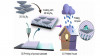
Surface engineering played an important role in the thermal control of spacecraft. In the absence of atmosphere, the temperature of a spacecraft is controlled by passive thermal control techniques utilizing the optical properties of its components. The requisite optical properties were achieved with proper surface modification. The passive system does not involve any relative movement of its parts and does not require external power for operation. This eliminates the possibility of its failure. The spacecraft modules were isolated from the harsh space environment (deep cold space) by multilayer insulation (MLI). MLI consists of alternating layers of heat reflecting radiation shields (thin aluminized polyester film) separated by low conductance spacers (polyester net). The internal generated heat is radiated to outer space by the optical windows called optical solar reflectors (OSR). OSR comprises a thin sheet of glass or quartz, silverized or aluminized on the back side by vacuum evaporation. OSR reflects the heat generated by various components of spacecraft to outer space. Solar reflectors typically occupy the areas where high heat dissipating equipment are located, e.g., traveling tube wave amplifier, output multiplexer and batteries. In addition, thermal control of various subsystems was achieved by the application of coatings with known optical properties. The temperature gradient within the module or instrument was minimized by application of high emittance black coatings on its components. These coatings improve the radiative coupling across the package. The radiative isolation can be achieved by low emittance metallic coatings. Some of the internal components of the spacecraft generate excessive heat, while others face deep, cold space. Black coatings (e.g., black anodizing, black painting) having high thermal emittance were applied in these areas to improve heat radiation characteristics.
Mission Profile
The launch vehicle initially injected Chandrayaan-3 stack in an Earth parking orbit of 170 x 36,500 km. Thereafter six Earth Bound Maneuvers (EBMs) were performed with the propulsion module engine to propel the composite craft farther away from the Earth and closer to the Moon. The final burn served as the Trans-Lunar Injection (TLI)-journey of craft towards the Moon. This was followed by Lunar Orbit Insertion (LOI), capturing the Moon and placing the composite craft into lunar parking orbit of about 164 x 18,074 km. Thereafter completing five Lunar Bound Maneuvers (LBM’s) spacecraft entered into polar 153 x 163 km Moon orbit. The lander module was then separated from the propulsion module, and de-boosted to 25 x 134 km orbit. Thereafter the landing operation of about 15 minutes was conducted autonomously. The commands were generated based on the precise measurement of Lander’s velocity and height from on-board instruments, including cameras photographing the lunar terrain. The measurements were updated in real time automatically. There were two phases of lunar descent; rough braking and fine braking. Rough Braking burn carried out at the perilune (nearest point to Moon), to reduce the horizontal velocity of the lander. Through this burn the horizontal velocity was reduced and altitude was lowered from 25 km to 7.4 km by firing the four corner liquid engines. Subsequently the orientation of the lander was changed from horizontal to vertical. In fine braking, the Lander descended vertically from 7.4 km to 100 m and its velocity was gradually reduced to < 2 m/sec. Fine braking starts with simultaneously switching on the two diagonal liquid engines. The horizontal movement (side wise move) of the Lander was controlled by firing the small 50 N thrusters. Before final landing, Vikram performed hovering, taking the photograph of the landing site and matched it with already stored images acquired by Chandrayaan-2 Orbiter high-resolution camera (OHRC). This was performed to ensure the safe landing at the predefined place. After confirming this Vikram descended slowly by reducing vertical thrust. At 4 m height the thrust was cut off, Vikram was in free fall with touch down velocity of ~ 1 m/sec.
The entire process from launching of Chandrayaan-3 to the landing of Vikram on the Moon took about 42 days. One may ask that 54 years ago (July 16, 1969), Apollo 11 launched by the Saturn V rocket had reached the Moon in just 51 hours and 49 minutes. Why did the Chandrayaan-3 take 42 days? Once the rockets escape the earth, it needs a velocity of 11.2 km/s to make further progress. India does not have such a powerful rocket, hence a sling-shot mechanism was adopted, where the spacecraft’s orbit is raised in multiple burns. The process is slow, but it provides ample opportunities for course correction, and is highly cost effective. Just before it was put in hibernation mode to survive the approaching lunar night, on September 4, 2023 Vikram successfully underwent a hop experiment. On command, it fired the engines, elevated itself by about 40 cm as expected and landed safely at a distance of 30–40 cm away. Deployed ramp, ChaSTE and ILSA were folded back and redeployed successfully. In-situ experiments by ChaSTE, RAMBHA-LP and ILSA payloads were performed at the new location. All the payloads were switched off while the receivers were kept on. Once the solar power depleted and the battery drained Vikram fell asleep next to Pragyan. This is because they do not have the Radioisotope Heater Units (RHUs) essential for their survival in extreme cold lunar nights. Against all odds there was hope for their awakening on the next lunar day, around September 22, 2023, but as expected this did not happen. However, all the objectives set for Chandrayaan-3 have been successfully achieved.
Conclusion
After the successful landing on the Moon on August 23, 2023, Chandrayaan-3 Vikram became the first probe to land near the lunar south pole, and India is the fourth country to achieve a soft lunar landing, after the United States, the former Soviet Union and China. The mission will shed light on a completely unexplored unique geology and composition of the South Polar Region of the Moon.
REFERENCES:
[1] A.K. Sharma: Chandrayaan-2 – What went wrong with the Lander? Feature Article, Science Reporter, 56, no. 11, (2019), 20-23, https://nopr.niscpr.res.in/bitstream/123456789/51218/1/SR%2056%2811%29%2020-23.pdf
[2] Chandrayaan-3: https://www.isro.gov.in/Chandrayaan3.html
[3] A.K. Sharma: Chandrayaan-3: India’s Quest for the Moon-Cover Story, Science Reporter, 60, no. 8, (2023), 14-19,https://nopr.niscpr.res.in/bitstream/123456789/62340/1/SR%2060%2808%29%2014-19.pdf
[4] A.K. Sharma: Surface engineering for thermal control of spacecraft, Surf. Eng., 21, no. 3, (2005), 249-253,doi: 10.1179/174329405X50118